MA single-gap expansion joint
Profiled edge beams and a rubber seal for bridge deck movement.
View product
HUAWEI HELI
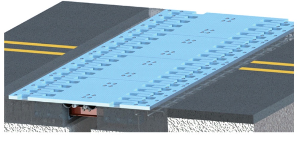
WBF bridge expansion system with intermeshing deck plates.
The WBF series is presented with its structural arrangement, component details and model designation. Selection considers the required deck movement and the interfaces with the bridge deck.
Configuration & selection
Deck-plate and support configuration
Movement and anchorage requirements
For selection, send the design loads, movement requirements and connection drawings. Confirm the model, dimensions and interfaces against your project drawings.
Bridge deck joints requiring multidirectional movement, including urban bridges and larger-movement applications.
Each module includes edge and center comb plates, a movement box, elastic supports, stainless-steel plates and waterproof seals. Specify total movement, horizontal and vertical rotations, skew angle, temperature class and deck recess.
WBF is presented as a patented family of standard bridge components developed with reference to JT/T 327-2016 and related requirements, for highway, municipal and rail-transit bridges. The design combines features of modular steel joints, ordinary comb joints and unit-type multidirectional comb joints.
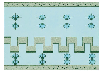
A symmetrical, segmented arrangement places one or more centre comb plates between two edge comb plates. Centre-plate width follows the bridge gap, and rotation of elastic elements permits angle changes. The separate centre plate aids installation and replacement. Symmetry simplifies recess preparation and reduces directional differences in vehicle impact.
JTG D60; JTG 3362-2018; JTG B02-2013; TB 10002.1-2005; TB 10002.2-2005; TB 10002.3-2005; GB 50111-2006; GB 50017-2003; GB 50017-2017; JTG D64-2015; JT/T 327-2016; JT/T 723-2008; JTJ 041-2000; JTG F80/1-2004. These are the supplied catalog’s design-reference editions, covering road/rail bridge design, seismic design, steel structures, expansion joints, construction and quality assessment.
Each unit contains two edge comb plates with welded stainless-steel plates, one or more centre plates, two or more movement-support/control systems, two or more elastic elements, two seal-seat plates and two waterproof seals. The unit is configured with one centre plate and two support systems. The unit arrangement facilitates manufacture, transport and installation. Solid concrete placement around the recess differs from hollow arrangements at conventional movement-system ends; symmetrical sides simplify design and casting.
The support/control system improves the load path and provides space for elastic elements. These elements connect the centre plate to the control system, allowing multidirectional movement, energy absorption and resistance to rebound. Each centre plate is supported by at least two control systems, each with one or more bolted elastic elements. Independent centre plates span the gap and accommodate three-dimensional girder-end changes through elastic deformation.
The seal-seat plates connect to the upper plates of the elastic elements, linking the individual control systems and centre-plate units. Dedicated grooves make seals easier to install and replace.
The catalog positions the system as combining comb-joint and modular-steel-joint advantages, with cost below conventional multidirectional comb joints of equivalent performance and slightly above modular steel joints. Pricing depends on the selected configuration and project requirements.
Across the bridge, repeated modules contain edge-plate assemblies, centre-plate assemblies, movement boxes, elastic supports, waterproof seals, stainless-steel plates and seal-seat plates.
| No. | Component |
|---|---|
| 1 | Edge comb plate |
| 2 | Stainless-steel plate |
| 3 | Centre comb plate |
| 4 | Elastic element |
| 5 | Movement box |
| 6 | Waterproof rubber seal |
| 7 | Seal-seat plate |
The model code lists WBF, movement range in mm, skew angle in degrees (omitted at 0°), horizontal/vertical rotation in rad and suffix F for the cold-resistant version. The normal-temperature version has no suffix.
The movement mechanism is separated from the concrete and positioned within the girder-end gap. It accommodates longitudinal, transverse, vertical and torsional movement, particularly for large and very large displacement applications.
MA-C/E/F/L joints use hot-rolled steel profiles and are described for movements up to 80 mm. MB joints comprise edge beams, centre beams, crossbeams and a movement-control mechanism; this overview gives an 80–1200 mm range. Select the movement range for the specified MB model.
The code identifies the joint series, profile shape, movement in mm and rubber material: NR = natural rubber; CR = chloroprene rubber. The printed examples describe C-profile 60 mm CR, F-profile 80 mm NR and MZL modular 480 mm NR joints.
The modular arrangement separates the load-carrying structure from the movement-control system so that load transfer and uniform movement do not interfere with each other.
Calculate bridge movement, allow an appropriate reserve and consider the available gap and anchorage at girder/slab ends. Supply the bridge cross-section, crossfall, footway, safety strip and barrier positions/dimensions; construction timing and installation-temperature range; and any special requirements. If no setting value is supplied, the factory presets the joint at half its rated maximum movement, citing JT/T 327-2016.
Joints are assembled to the design before transport. Where transport length or other restrictions prevent delivery as one piece, sectional manufacture is possible. Store near the installation location on supports at least 300 mm above ground.
Where the crossing direction is oblique, anchor reinforcement and movement-control boxes may be arranged at an angle to the edge beam. These installation instructions cover 0–80 mm joints and MB 160–400 mm modular joints. The angle follows the bridge skew. Drawing notation: h = recess depth; b = recess width; α = angle between anchor reinforcement and edge beam. Select the MA-C, MA-F or MA-L arrangement to suit the actual recess, or provide special drawings for design. The 160 mm section refers to the wider 160–1200 mm installation drawing series.
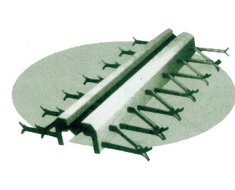
Profiled edge beams and a rubber seal for bridge deck movement.
View product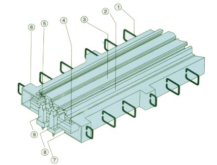
No products match your search.