MA single-gap expansion joint
Profiled edge beams and a rubber seal for bridge deck movement.
View product
HUAWEI HELI
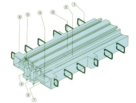
Modular expansion joint with multiple movement gaps.
The MB series accommodates bridge deck movement through a modular beam and sealing arrangement. Model-specific drawings show the overall dimensions, supporting components and installation recess.
Configuration & selection
Modular movement configurations
Installation recess and anchorage details
For selection, send the design loads, movement requirements and connection drawings. Confirm the model, dimensions and interfaces against your project drawings.
Road bridges with larger deck movements requiring several coordinated expansion gaps.
Select the number of modules and model using the total design movement. The product specification describes an 80–2,000 mm family; actual model dimensions, recess size, skew angle and installation gap must be checked against the project.
MB joints combine intermediate steel beams and 80 mm sealing strips. The product description states application to highway bridge movements of 80–2000 mm; the installation configurations listed here cover models through 1200 mm.
| No. | Component |
|---|---|
| 1 | Anchor reinforcement |
| 2 | Edge beam |
| 3 | Centre beam |
| 4 | Crossbeam |
| 5 | Waterproof rubber seal |
| 6 | Control box |
| 7 | Compression bearing |
| 8 | Hold-down bearing |
| 9 | Hanger |
A linkage between crossbeams controls uniform centre-beam movement. Installation configurations include the 160, 240, 320 and 400 mm models, their recess dimensions and bridge-deck surfacing.
Modular-joint installation configurations cover nominal movements 480, 560, 640, 720 and 800 mm. The drawings identify the reserved recess, bridge-deck surfacing, anchor positions, section depths and variable widths. Dimensions are in mm.
Installation configurations cover nominal movements 880, 960, 1040, 1120 and 1200 mm. The drawings identify reserved recesses, deck surfacing, anchorage, depths and width ranges.
MA-C/E/F/L joints use hot-rolled steel profiles and are described for movements up to 80 mm. MB joints comprise edge beams, centre beams, crossbeams and a movement-control mechanism; this overview gives an 80–1200 mm range. Select the movement range for the specified MB model.
The code identifies the joint series, profile shape, movement in mm and rubber material: NR = natural rubber; CR = chloroprene rubber. The printed examples describe C-profile 60 mm CR, F-profile 80 mm NR and MZL modular 480 mm NR joints.
The modular arrangement separates the load-carrying structure from the movement-control system so that load transfer and uniform movement do not interfere with each other.
Calculate bridge movement, allow an appropriate reserve and consider the available gap and anchorage at girder/slab ends. Supply the bridge cross-section, crossfall, footway, safety strip and barrier positions/dimensions; construction timing and installation-temperature range; and any special requirements. If no setting value is supplied, the factory presets the joint at half its rated maximum movement, citing JT/T 327-2016.
Joints are assembled to the design before transport. Where transport length or other restrictions prevent delivery as one piece, sectional manufacture is possible. Store near the installation location on supports at least 300 mm above ground.
Where the crossing direction is oblique, anchor reinforcement and movement-control boxes may be arranged at an angle to the edge beam. These installation instructions cover 0–80 mm joints and MB 160–400 mm modular joints. The angle follows the bridge skew. Drawing notation: h = recess depth; b = recess width; α = angle between anchor reinforcement and edge beam. Select the MA-C, MA-F or MA-L arrangement to suit the actual recess, or provide special drawings for design. The 160 mm section refers to the wider 160–1200 mm installation drawing series.
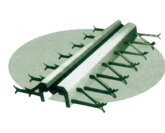
Profiled edge beams and a rubber seal for bridge deck movement.
View product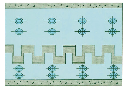
No products match your search.