

GPZ (II) pot bearing
Pot rubber bearing with fixed, guided and multidirectional options.
A confined elastomeric pad transfers vertical load inside a steel pot. The bearing accommodates rotation; sliding assemblies provide the movement required by the bridge.
Configuration & selection
GD — fixed
DX — guided sliding
SX — multidirectional sliding
For selection, send the design loads, movement requirements and connection drawings. Confirm the model, dimensions and interfaces against your project drawings.
Applications
Medium- and long-span road bridges requiring vertical load transfer, deck rotation and controlled horizontal movement.
Key features
- Confined elastomer supports vertical loads inside a compact steel pot.
- Sliding surfaces accommodate movement; guides and fixed restraints define the force path.
- Low structural height helps coordinate the bearing with the pier and deck interface.
Technical specifications
GD fixed, DX guided and SX multidirectional configurations. The catalog lists 0.8–60 MN vertical-load classes and a design rotation of at least 0.02 rad. Normal-temperature and cold-resistant options are listed; displacement and anchorage dimensions depend on the selected model.
Detailed technical information
GPZ (II): description and performance
The product specification describes this highway bridge pot-bearing series as designed to JT/T 391-2019, with reference to BS 5400 Part 9, Bridge Bearings, and EN 1337-5, Pot Bearings, to meet bridge structural requirements.
| Parameter | Value / condition |
|---|---|
| Vertical design load | 0.8–60 MN in 31 classes |
| Design rotation | At least 0.02 rad (approximately 1.15°) |
| Horizontal resistance | 10% of vertical capacity: all directions for GD; restrained direction for DX |
| Movement | See the configuration-specific dimensional tables |
| Normal-temperature version C | −25°C to +60°C; design friction coefficient μ ≤ 0.03 |
| Cold-resistant version F | −40°C to +60°C; design friction coefficient μ ≤ 0.05 |
| Special design | Available where movement or vertical/horizontal loads exceed the listed range |
The drawings identify SX multidirectional, DX guided and GD fixed configurations.
GPZ(II) SX dimensions
Dimensions and movement are in mm unless another unit is shown. Dimension symbols follow the manufacturer’s drawing.
| Model | A at e=±50 | A at e=±100 | A at e=±150 | A at e=±200 | A at e=±250 | A at e=±300 | A′ at e=±50 | A′ at e=±100 | A′ at e=±150 | A′ at e=±200 | A′ at e=±250 | A′ at e=±300 | B | B′ | C(D) | C′(D′) | H | Transverse movement |
|---|---|---|---|---|---|---|---|---|---|---|---|---|---|---|---|---|---|---|
| GPZ(II)0.8SX | 320 | 420 | 520 | — | — | — | 280 | 380 | 480 | — | — | — | 300 | 260 | 245 | 200 | 75 | ±40 |
| GPZ(II)1SX | 340 | 440 | 540 | — | — | — | 300 | 400 | 500 | — | — | — | 320 | 280 | 270 | 225 | 80 | ±40 |
| GPZ(II)1.25SX | 360 | 460 | 560 | — | — | — | 320 | 420 | 520 | — | — | — | 340 | 300 | 300 | 250 | 85 | ±40 |
| GPZ(II)1.5SX | 380 | 480 | 580 | — | — | — | 340 | 440 | 540 | — | — | — | 360 | 320 | 330 | 275 | 90 | ±40 |
| GPZ(II)2SX | 420 | 520 | 620 | — | — | — | 380 | 480 | 580 | — | — | — | 400 | 360 | 385 | 320 | 100 | ±40 |
| GPZ(II)2.5SX | 460 | 560 | 660 | — | — | — | 420 | 520 | 620 | — | — | — | 440 | 400 | 425 | 355 | 105 | ±40 |
| GPZ(II)3SX | 490 | 590 | 690 | — | — | — | 440 | 540 | 640 | — | — | — | 465 | 415 | 465 | 385 | 110 | ±40 |
| GPZ(II)3.5SX | — | 620 | 720 | 820 | — | — | — | 570 | 670 | 770 | — | — | 500 | 450 | 500 | 415 | 115 | ±40 |
| GPZ(II)4SX | — | 640 | 740 | 840 | — | — | — | 590 | 690 | 790 | — | — | 540 | 490 | 540 | 450 | 130 | ±40 |
| GPZ(II)5SX | — | 690 | 790 | 890 | — | — | — | 630 | 730 | 830 | — | — | 600 | 540 | 600 | 500 | 140 | ±40 |
| GPZ(II)6SX | — | 740 | 840 | 940 | — | — | — | 680 | 780 | 880 | — | — | 655 | 595 | 655 | 540 | 150 | ±40 |
| GPZ(II)7SX | — | 780 | 880 | 980 | — | — | — | 720 | 820 | 920 | — | — | 705 | 640 | 705 | 580 | 160 | ±40 |
| GPZ(II)8SX | — | 810 | 910 | 1010 | — | — | — | 735 | 835 | 935 | — | — | 755 | 680 | 755 | 630 | 170 | ±40 |
| GPZ(II)9SX | — | 850 | 950 | 1050 | — | — | — | 775 | 875 | 975 | — | — | 800 | 720 | 800 | 660 | 180 | ±40 |
| GPZ(II)10SX | — | — | 980 | 1080 | 1180 | — | — | — | 905 | 1005 | 1105 | — | 845 | 765 | 845 | 700 | 190 | ±40 |
| GPZ(II)12.5SX | — | — | 1060 | 1160 | 1260 | — | — | — | 970 | 1070 | 1170 | — | 945 | 855 | 945 | 780 | 205 | ±40 |
| GPZ(II)15SX | — | — | 1130 | 1230 | 1330 | — | — | — | 1040 | 1140 | 1240 | — | 1030 | 940 | 1030 | 860 | 220 | ±40 |
| GPZ(II)17.5SX | — | — | 1190 | 1290 | 1390 | — | — | — | 1100 | 1200 | 1300 | — | 1110 | 1020 | 1110 | 920 | 235 | ±40 |
| GPZ(II)20SX | — | — | 1250 | 1350 | 1450 | — | — | — | 1150 | 1250 | 1350 | — | 1190 | 1090 | 1190 | 990 | 250 | ±40 |
| GPZ(II)22.5SX | — | — | 1310 | 1410 | 1510 | — | — | — | 1210 | 1310 | 1410 | — | 1260 | 1160 | 1260 | 1050 | 260 | ±40 |
| GPZ(II)25SX | — | — | 1360 | 1460 | 1560 | — | — | — | 1250 | 1350 | 1450 | — | 1340 | 1230 | 1340 | 1110 | 270 | ±40 |
| GPZ(II)27.5SX | — | — | 1410 | 1510 | 1610 | — | — | — | 1300 | 1400 | 1500 | — | 1410 | 1300 | 1410 | 1170 | 280 | ±40 |
| GPZ(II)30SX | — | — | 1470 | 1560 | 1660 | — | — | — | 1360 | 1450 | 1550 | — | 1470 | 1360 | 1470 | 1220 | 290 | ±40 |
| GPZ(II)32.5SX | — | — | — | 1610 | 1710 | 1810 | — | — | — | 1490 | 1590 | 1690 | 1525 | 1400 | 1525 | 1270 | 300 | ±50 |
| GPZ(II)35SX | — | — | — | 1650 | 1750 | 1850 | — | — | — | 1530 | 1630 | 1730 | 1585 | 1460 | 1585 | 1320 | 310 | ±50 |
| GPZ(II)37.5SX | — | — | — | 1690 | 1790 | 1890 | — | — | — | 1570 | 1670 | 1770 | 1645 | 1520 | 1645 | 1370 | 320 | ±50 |
| GPZ(II)40SX | — | — | — | 1730 | 1830 | 1930 | — | — | — | 1610 | 1710 | 1810 | 1690 | 1570 | 1690 | 1410 | 330 | ±50 |
| GPZ(II)45SX | — | — | — | 1810 | 1910 | 2010 | — | — | — | 1680 | 1780 | 1880 | 1800 | 1660 | 1800 | 1500 | 345 | ±50 |
| GPZ(II)50SX | — | — | — | 1890 | 1990 | 2090 | — | — | — | 1760 | 1860 | 1960 | 1890 | 1750 | 1890 | 1570 | 360 | ±50 |
| GPZ(II)55SX | — | — | — | 1990 | 2060 | 2160 | — | — | — | 1850 | 1920 | 2020 | 1990 | 1850 | 1990 | 1660 | 375 | ±50 |
| GPZ(II)60SX | — | — | — | 2070 | 2130 | 2230 | — | — | — | 1930 | 1990 | 2090 | 2070 | 1930 | 2070 | 1720 | 390 | ±50 |
e denotes longitudinal movement.
GPZ(II) DX dimensions
| Model | A at e=±50 | A at e=±100 | A at e=±150 | A at e=±200 | A at e=±250 | A at e=±300 | A′ at e=±50 | A′ at e=±100 | A′ at e=±150 | A′ at e=±200 | A′ at e=±250 | A′ at e=±300 | B | B′ | C(D) | C′ | D′ | H |
|---|---|---|---|---|---|---|---|---|---|---|---|---|---|---|---|---|---|---|
| GPZ(II)0.8DX | 320 | 420 | 520 | — | — | — | 280 | 380 | 480 | — | — | — | 315 | 220 | 265 | 230 | 180 | 75 |
| GPZ(II)1DX | 340 | 440 | 540 | — | — | — | 300 | 400 | 500 | — | — | — | 340 | 245 | 290 | 250 | 200 | 80 |
| GPZ(II)1.25DX | 360 | 460 | 560 | — | — | — | 320 | 420 | 520 | — | — | — | 370 | 275 | 320 | 280 | 230 | 85 |
| GPZ(II)1.5DX | 380 | 480 | 580 | — | — | — | 340 | 440 | 540 | — | — | — | 410 | 300 | 350 | 310 | 260 | 90 |
| GPZ(II)2DX | 420 | 520 | 620 | — | — | — | 380 | 480 | 580 | — | — | — | 460 | 350 | 400 | 360 | 310 | 100 |
| GPZ(II)2.5DX | 460 | 560 | 660 | — | — | — | 420 | 520 | 620 | — | — | — | 505 | 395 | 445 | 405 | 355 | 105 |
| GPZ(II)3DX | 485 | 585 | 685 | — | — | — | 435 | 535 | 635 | — | — | — | 565 | 425 | 485 | 435 | 370 | 110 |
| GPZ(II)3.5DX | — | 620 | 720 | 820 | — | — | — | 570 | 670 | 770 | — | — | 600 | 460 | 520 | 470 | 400 | 115 |
| GPZ(II)4DX | — | 640 | 740 | 840 | — | — | — | 590 | 690 | 790 | — | — | 635 | 485 | 555 | 505 | 435 | 130 |
| GPZ(II)5DX | — | 690 | 790 | 890 | — | — | — | 635 | 735 | 835 | — | — | 710 | 545 | 620 | 560 | 480 | 140 |
| GPZ(II)6DX | — | 740 | 840 | 940 | — | — | — | 680 | 780 | 880 | — | — | 770 | 600 | 680 | 620 | 540 | 150 |
| GPZ(II)7DX | — | 780 | 880 | 980 | — | — | — | 720 | 820 | 920 | — | — | 820 | 650 | 730 | 670 | 590 | 160 |
| GPZ(II)8DX | — | 810 | 910 | 1010 | — | — | — | 740 | 840 | 940 | — | — | 890 | 690 | 780 | 710 | 620 | 170 |
| GPZ(II)9DX | — | 850 | 950 | 1050 | — | — | — | 780 | 880 | 980 | — | — | 935 | 725 | 825 | 755 | 665 | 180 |
| GPZ(II)10DX | — | — | 980 | 1080 | 1180 | — | — | — | 910 | 1010 | 1110 | — | 985 | 770 | 875 | 800 | 715 | 190 |
| GPZ(II)12.5DX | — | — | 1060 | 1160 | 1260 | — | — | — | 980 | 1080 | 1180 | — | 1100 | 860 | 970 | 890 | 780 | 205 |
| GPZ(II)15DX | — | — | 1130 | 1230 | 1330 | — | — | — | 1050 | 1150 | 1250 | — | 1190 | 950 | 1060 | 980 | 870 | 220 |
| GPZ(II)17.5DX | — | — | 1190 | 1290 | 1390 | — | — | — | 1105 | 1205 | 1305 | — | 1295 | 1030 | 1145 | 1060 | 935 | 235 |
| GPZ(II)20DX | — | — | 1250 | 1350 | 1450 | — | — | — | 1155 | 1255 | 1355 | — | 1375 | 1100 | 1225 | 1130 | 1000 | 250 |
| GPZ(II)22.5DX | — | — | 1310 | 1410 | 1510 | — | — | — | 1220 | 1320 | 1420 | — | 1450 | 1180 | 1300 | 1210 | 1080 | 260 |
| GPZ(II)25DX | — | — | 1370 | 1460 | 1560 | — | — | — | 1270 | 1360 | 1460 | — | 1540 | 1240 | 1370 | 1270 | 1120 | 270 |
| GPZ(II)27.5DX | — | — | 1440 | 1510 | 1610 | — | — | — | 1340 | 1410 | 1510 | — | 1610 | 1310 | 1440 | 1340 | 1190 | 280 |
| GPZ(II)30DX | — | — | 1500 | 1560 | 1660 | — | — | — | 1400 | 1460 | 1560 | — | 1670 | 1370 | 1500 | 1400 | 1250 | 290 |
| GPZ(II)32.5DX | — | — | — | 1610 | 1710 | 1810 | — | — | — | 1500 | 1600 | 1700 | 1750 | 1420 | 1560 | 1450 | 1270 | 300 |
| GPZ(II)35DX | — | — | — | 1650 | 1750 | 1850 | — | — | — | 1540 | 1640 | 1740 | 1810 | 1480 | 1620 | 1510 | 1330 | 310 |
| GPZ(II)37.5DX | — | — | — | 1690 | 1790 | 1890 | — | — | — | 1580 | 1680 | 1780 | 1890 | 1540 | 1680 | 1570 | 1370 | 320 |
| GPZ(II)40DX | — | — | — | 1730 | 1830 | 1930 | — | — | — | 1620 | 1720 | 1820 | 1940 | 1590 | 1730 | 1620 | 1420 | 330 |
| GPZ(II)45DX | — | — | — | 1840 | 1910 | 2010 | — | — | — | 1710 | 1780 | 1880 | 2070 | 1680 | 1840 | 1710 | 1510 | 345 |
| GPZ(II)50DX | — | — | — | 1930 | 1990 | 2090 | — | — | — | 1800 | 1860 | 1960 | 2160 | 1770 | 1930 | 1800 | 1600 | 360 |
| GPZ(II)55DX | — | — | — | 2030 | 2060 | 2160 | — | — | — | 1890 | 1920 | 2020 | 2280 | 1860 | 2030 | 1890 | 1680 | 375 |
| GPZ(II)60DX | — | — | — | 2110 | 2130 | 2230 | — | — | — | 1970 | 1990 | 2090 | 2360 | 1940 | 2110 | 1970 | 1760 | 390 |
GPZ(II) GD fixed dimensions
| Model | A = B = C = D (mm) | A′ = B′ = C′ = D′ (mm) | H (mm) |
|---|---|---|---|
| GPZ(II)0.8GD | 250 | 210 | 75 |
| GPZ(II)1GD | 280 | 235 | 80 |
| GPZ(II)1.25GD | 310 | 260 | 85 |
| GPZ(II)1.5GD | 340 | 290 | 90 |
| GPZ(II)2GD | 390 | 330 | 95 |
| GPZ(II)2.5GD | 435 | 370 | 100 |
| GPZ(II)3GD | 475 | 400 | 105 |
| GPZ(II)3.5GD | 510 | 430 | 110 |
| GPZ(II)4GD | 545 | 460 | 115 |
| GPZ(II)5GD | 610 | 520 | 130 |
| GPZ(II)6GD | 670 | 570 | 140 |
| GPZ(II)7GD | 720 | 610 | 150 |
| GPZ(II)8GD | 770 | 650 | 155 |
| GPZ(II)9GD | 815 | 690 | 160 |
| GPZ(II)10GD | 860 | 730 | 170 |
| GPZ(II)12.5GD | 960 | 810 | 185 |
| GPZ(II)15GD | 1050 | 890 | 200 |
| GPZ(II)17.5GD | 1135 | 960 | 210 |
| GPZ(II)20GD | 1220 | 1040 | 230 |
| GPZ(II)22.5GD | 1290 | 1100 | 240 |
| GPZ(II)25GD | 1360 | 1150 | 250 |
| GPZ(II)27.5GD | 1430 | 1220 | 260 |
| GPZ(II)30GD | 1490 | 1270 | 270 |
| GPZ(II)32.5GD | 1550 | 1320 | 280 |
| GPZ(II)35GD | 1610 | 1370 | 290 |
| GPZ(II)37.5GD | 1670 | 1420 | 300 |
| GPZ(II)40GD | 1720 | 1460 | 310 |
| GPZ(II)45GD | 1830 | 1560 | 320 |
| GPZ(II)50GD | 1920 | 1630 | 335 |
| GPZ(II)55GD | 2020 | 1720 | 350 |
| GPZ(II)60GD | 2100 | 1790 | 365 |
GPZ(II) anchor pockets
| Model range | Pocket diameter D (mm) | Pocket depth H (mm) |
|---|---|---|
| GPZ(II)0.8–4 | 80 | 300 |
| GPZ(II)5–7 | 100 | 360 |
| GPZ(II)8–10 | 120 | 360 |
| GPZ(II)12.5–17.5 | 140 | 420 |
| GPZ(II)20–22.5 | 160 | 420 |
| GPZ(II)25–30 | 180 | 480 |
| GPZ(II)32.5–40 | 200 | 480 |
| GPZ(II)45–50 | 220 | 540 |
| GPZ(II)55–60 | 240 | 540 |
Pot bearings: series and model codes
Pot bearings combine steel components and rubber elements. They provide high load capacity, substantial horizontal movement and flexible rotation in a compact, lightweight assembly with a low structural height, for medium- and long-span bridges.
| Series | Description | GD | DX | SX |
|---|---|---|---|---|
| GPZ (II) | Highway bridge pot rubber bearing | Fixed | Guided sliding | Multidirectional sliding |
| GPZ (KZ) | Seismic highway bridge pot rubber bearing | Fixed | Guided sliding | Multidirectional sliding |
| GPZ (2019) | 2019 highway bridge pot bearing | Fixed | Guided sliding | Multidirectional sliding |
The model identifies the series, vertical design load in MN, movement configuration, longitudinal movement in mm and, where applicable, the cold-resistant suffix F. The normal-temperature version has no suffix. Example: GPZ (2019) 3SX ±100-F denotes a cold-resistant, multidirectional bearing with a 3 MN vertical design load and ±100 mm principal movement.
Pot and spherical bearings: plinths and bolted installation
Bearing plinth
Provide a bearing plinth at the pier or abutment for every bearing, whether the girder is cast in situ or precast. It supports installation quality and access for adjustment, inspection and replacement. Its plan must support the superstructure load; the catalog generally requires both length and width to exceed the bearing base-plate dimensions by more than 200 mm. Height is to exceed 60 mm, allowing space for replacement jacks. Slope the perimeter to prevent standing water.
Reinforcement is to satisfy the local compression provisions cited in JTG 3362-2018. Weld the vertical reinforcement securely to the pier/abutment reinforcement. Use concrete of at least C40, and level and clean the plinth top.
Cast-in-situ girders: sleeve-and-bolt connections
- A. Form sleeve pockets in the plinth. The hole diameter and depth are to exceed the sleeve/rod diameter and length by 50–60 mm.
- B. Mark the design bearing centre lines on the plinth.
- C. Bearings are supplied centrally assembled. Where the design requires it, preset the guided or multidirectional bearing offset for the installation temperature, then secure the four connecting plates. No offset adjustment is needed in the absence of special requirements.
- D. Lift the complete bearing and insert bolts through the upper and lower plates into the sleeves. Certain fixed bearings require temporary removal of the four connecting plates and rotation of the top plate to reach the bolt holes, followed by restoration and tightening. Align both centre lines and insert the sleeves into the reserved pockets. Use four steel wedges to level the bearing; the base plate is to stand 20–50 mm above the plinth, with no more than 2 mm difference between the four corners.
Bolted installation: levelling and grouting
Align and level the bearing using temporary connecting plates, formwork and steel wedges, with the bearing plinth and pier as the supporting structure.
E. Fill the reserved sleeve pockets and the bedding beneath the bearing base plate with epoxy mortar or non-shrink mortar. After hardening, remove the four steel wedges and completely fill their voids with mortar. Ensure dense, continuous filling. The drawings show gravity grouting, removal of formwork/wedges and filling the wedge pockets.
Bolted installation: finishing and release
- F. After fitting the bolts, apply an additional coat of epoxy zinc-rich primer to the bolts/nuts and repair damaged bearing paint.
- G. Use the top bearing plate as part of the cast-in-situ girder formwork. Seal gaps around it with gauze or soft timber to prevent grout leakage; remove this packing with the formwork.
- H. Once the girder is integral and has reached design strength, remove the four connecting plates before prestressing. Where temporary connecting bolts are used, remove those bolts, so that normal rotation and movement are not restrained.
- I. For sliding bearings, clean the stainless-steel surface with alcohol or acetone. This completes the bearing installation.
Cast-in-situ girders: welded bearing connections
Welded installation may be used where embedded steel plates are provided in the pier/abutment and/or girder. The product specification describes two lower-plate arrangements: casting the embedded plate and anchors integrally with the support, or grouting reserved anchor/sleeve pockets and the bedding beneath the plate.
Integrally cast embedded lower plate
- Mark the design centre lines and establish the lower-plate elevation with a level. Weld a short reinforcing bar to the main corner reinforcement; its top marks the underside of the embedded plate, with an elevation error no greater than 1 mm. Transfer that level to short bars at the other three corners.
- Erect formwork and cast the support concrete densely.
- Lift the bearing onto the embedded plate and align the base-plate centre with the design centre. Use symmetrical intermittent welds and cooling measures to avoid overheating the internal rubber and PTFE components.
- Align and weld the top bearing plate to the upper embedded plate in the same way.
- Restore corrosion protection to welds and damaged paint.
- After the girder becomes integral and reaches design strength, remove the four connecting plates or temporary connecting bolts before prestressing.
Grouted lower plate
- Provide the plinth, sleeve pockets and centre lines as in steps A–B of the bolted installation.
- Lift and align the lower plate with the sleeves in the reserved pockets. Level it using four steel wedges, or levelling blocks of the same material and strength as the pocket grout, with height differences no greater than 1 mm. Set the plate 20–50 mm above the plinth and keep its four-corner height difference within 2 mm. For sliding bearings, identify the specified principal movement direction and follow the arrow marks. Weight the plate to prevent flotation.
Grouted plate details and precast-girder installation
After grouting the lower plate, lift and align the bearing, weld the lower and upper plates with controlled heat input, repair corrosion protection and remove temporary restraints after the girder reaches the required strength.
Precast girders
- Where sleeve pockets cannot readily be formed in the precast girder, embed a steel plate. Its length and width are to exceed the top bearing plate by more than 50 mm. Provide sufficient welded anchor reinforcement and suitable vent holes. Upper-plate sleeves are not used in this arrangement.
- Bolt or weld the bearing securely to the girder embedded plate. For welding, use symmetrical intermittent welds and cooling measures to protect the PTFE plate and silicone grease from overheating.
Precast installation completion and annual maintenance
- Insert the lower bolts through the base plate into the sleeves and tighten them. Lift the assembly into position on the plinth, using the pocket requirements in steps A–B.
- Adjust girder position and elevation with jacks, retaining a 20–50 mm gap beneath the base plate. Use non-shrink, high-strength grout of at least C40.
- Gravity-grout the bearing bedding and anchor pockets from the centre towards the perimeter until every side gap is full. Ensure dense filling.
- When grout reaches the specified strength, not less than 25 MPa, remove the formwork, inspect for leakage voids and fill any deficiencies.
- Remove all temporary bearing connecting plates or bolts.
- Remove temporary support jacks, clear surrounding debris and dust, repair weld/paint protection, and clean sliding stainless-steel surfaces with alcohol or acetone.
Inspection and maintenance
- Inspect and maintain at least once each year.
- Loosen and check bolts for shearing; clean and lubricate to prevent seizure, then retighten.
- Repair or replace cracked or damaged components.
- Record each bearing movement and check whether relative movements are consistent.
- Repaint steel areas with coating loss or rust.
- Clear debris from around the plinth and clean sliding stainless-steel surfaces.
- Check changes in bearing height to assess PTFE wear. If the bearing height changes by more than 3 mm, examine the remaining PTFE height h.
| Remaining height h | Action |
|---|---|
| h ≥ 1.0 mm | Normal inspection |
| 0.5 mm ≤ h < 1.0 mm | Increase inspection frequency |
| 0.2 mm < h < 0.5 mm | Increase inspection frequency further |
| h ≤ 0.2 mm | Expert assessment or replacement |
More bridge bearings
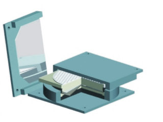

GPZ (2019) pot bearing
GPZ (2019) series for load transfer, rotation and bridge movement.
View product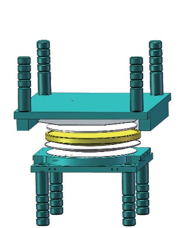
QZ spherical bearing
Spherical bearing for vertical load, rotation and horizontal movement.
View productNo products match your search.