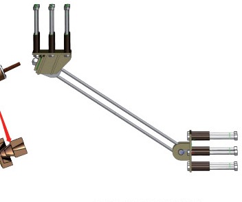
Composite energy-dissipating beam link
Flexible connection with a composite energy-dissipating arrangement.
View productFlexible bridge connection for excessive-movement restraint.
This Q-type configuration forms part of the flexible beam-link family. A flexible connection and energy-absorbing arrangement restrain excessive relative movement between bridge components.
Configuration & selection
Q-type connection layout
Free travel, buffer travel and anchorage
For selection, send the design loads, movement requirements and connection drawings. Confirm the model, dimensions and interfaces against your project drawings.
Bridge unseating-prevention layouts connecting girders or connecting a girder to an abutment or pier.
Select link force, free travel, buffer travel, installation angle and anchorage from the approved bridge design. The catalog recommends distributed, symmetric layouts and, where practical, horizontal girder-to-girder connections.
A flexible unseating-prevention device (FUPD) limits excessive movement that could allow the bridge superstructure to leave its pier or abutment. It acts as a final line of defence through flexible connection and buffered energy dissipation.
| Item | Catalog description |
|---|---|
| Ultimate capacity | Up to 5000 kN, using steel strands or wire ropes |
| Safety factor | ≥1.5 |
| Durability | Corrosion-protected steel; stated service life up to 50 years |
| Free stroke | ±200 to ±1200 mm |
| Buffer stroke | ±50 to ±500 mm |
| Installation angle | Type I: ±30°; Types II/III: ±5° |
| Economy | Simple rope/strand and connector construction; standardised selection and batch application |
| Maintenance | Replaceable key components including buffer elements and fork ends |
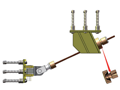
Three product types are illustrated: Q-type beam link, composite energy-dissipating beam link and wire-rope beam link. The quoted ranges describe the family and must be matched to the selected configuration.
| Stage | Behaviour |
|---|---|
| 1. Bearings | During small/moderate earthquakes, the system remains elastic and bearing movement stays within the intended range |
| 2. Sliding gap | As shaking increases, bearings undergo greater sliding within the designed clearance; bearing damage is permitted while other components are intended to remain elastic |
| 3. Restraints and unseating-prevention links | The load path changes from girder–bearing–pier to girder–restraint–pier; the pier may enter ductile response |

Flexible connection with a composite energy-dissipating arrangement.
View product
No products match your search.